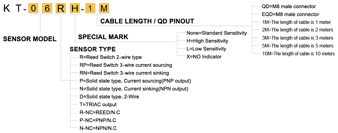
ORDERING INFORMATION
CONNECTION METHOD
2 Wire sensor connection

When connecting 2-wire sensors in series (AND), don’t exceed more than two sensors due to the internal voltage drop (Typical V drop=2.5 ~ 4V per switch). Excessive Voltage drop will cause non-operation of the load.
- When connecting solid state 2-wire sensors in parallel (OR), leakage current will increase and cause improper load operation.
- When connecting 2-wire reed sensors in parallel(OR), possible concurrent operation will cause dim LED illumination due to lower current distribution.
3 wire NPN connection

3 wire PNP connection

Reed SW. Type
When the piston’s magnet approaches the magnetic sensor, the internal reed switch will detect the change of magnetic field and close the contacts.

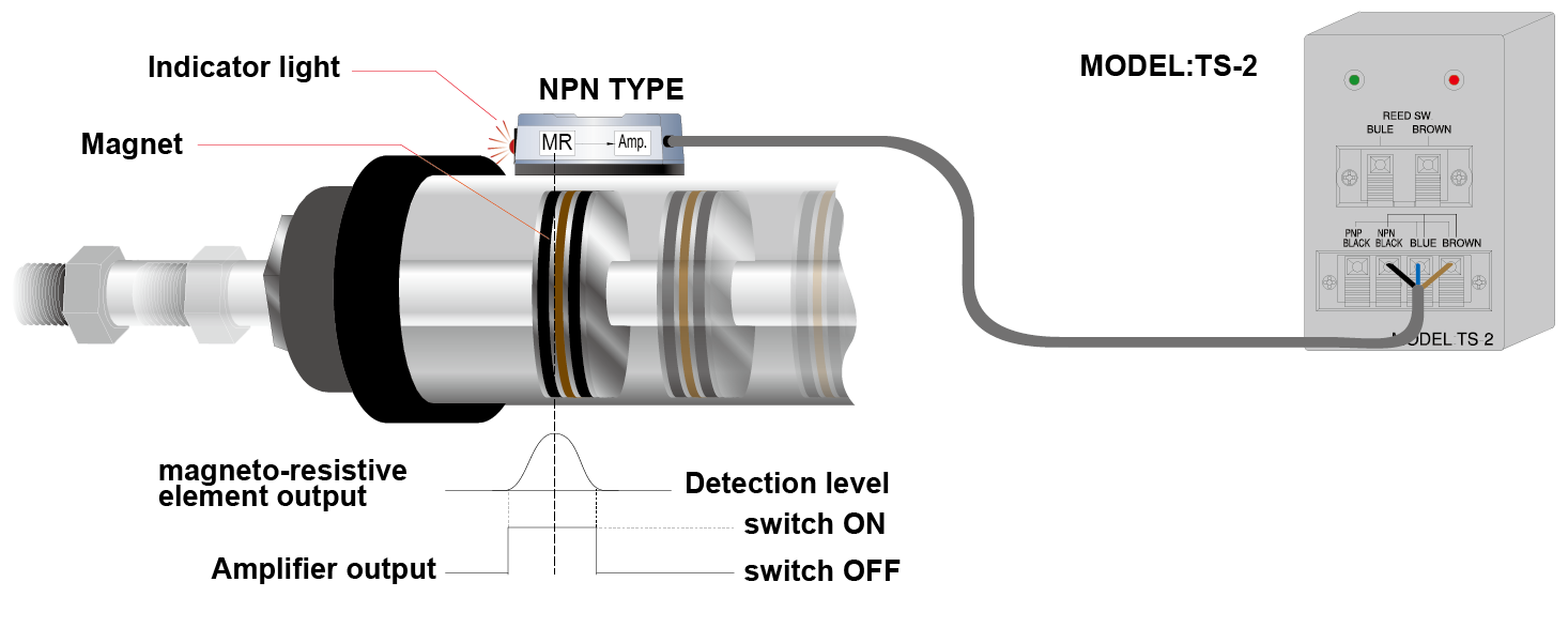
Solid State Type
When the piston’s magnet approaches the magnetic sensor, the internal magneto-resistive element candetect the change of magnetic field and cause a tiny voltage change. Switching output is achieved when this signal is amplified by the operation amplifier circuit in the magnetic sensor.
Solid State Type
How to install the Magnetic sensor
END OF STROKE DETECTION
STEP 1 Set the piston to the end of stroke position.
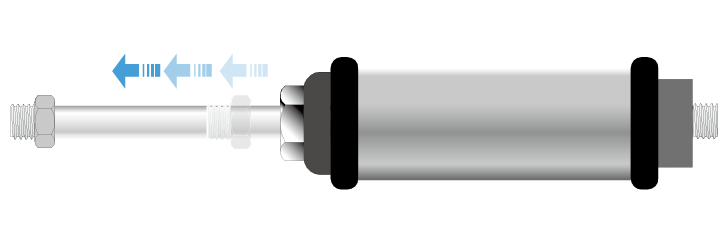
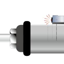
STEP 2 Slide the magnetic sensor forward and keep it close to the cylinder wall. Make a mark at the sensor turn-on point.
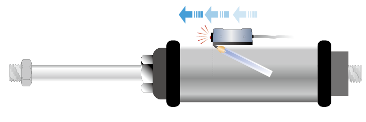
STEP 3 Slide the sensor forward continuously until the sensor turns off.
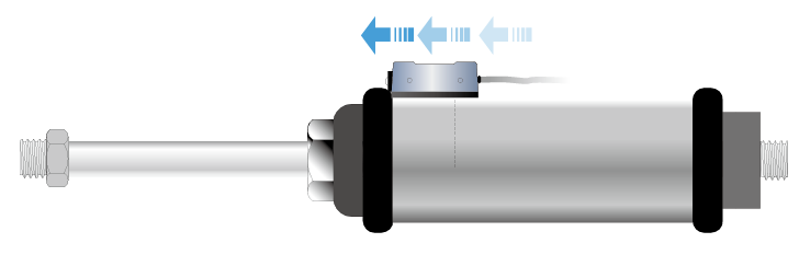
STEP 4 Slide the sensor backward until the sensor turns back on and make a mark.

STEP 5 The intermediate position between the 2 marks will be the most ideal position.
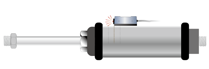
INTERMEDIATE STROKE POSITION
STEP 1 Set the piston to the required position.

STEP 2 Slide the magnetic sensor forward and keep it close to the cylinder wall. Make a mark at the sensor turn-on point.

STEP 3 Slide the sensor forward continuously until the sensor turns off.

STEP 4 Slide the sensor backward until the sensor turns back on and make a mark.

STEP 5 The intermediate position between the 2 marks will be the most ideal position.


