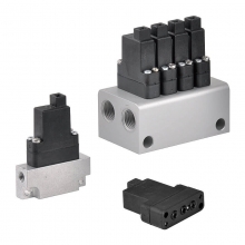
- Size 6
- Component series 6X
- Maximum operating pressure 350 bar
- Maximum flow 70 l/min
- Area of application according to NEC 505: Class I, Zone 1
- Type of protection of the valve solenoids: AEx e mb IIC T4 Gb according to ANSI / ISA 60079-7 ANSI / ISA 60079-18
Features:
- 4/3-, 4/2- or 3/2-way version
- For intended use in potentially explosive atmosphere
- Porting pattern according to ISO 4401-03-02-0-05
- Subplates available in FE/ZN version (see dimensions)
- Wet-pin DC solenoids
- Solenoid coil can be rotated by 90°
- Electrical connection as a single connection with pipe thread NPT 1/2″
- Manual override, optional
product description:
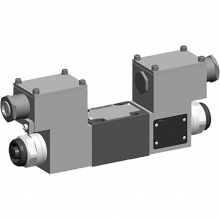
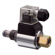
Directional valves of type WE are solenoid-actuated directional spool valves. They control the start, stop and direction of a flow.
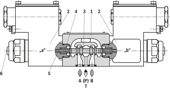
The directional valves basically consist of the housing (1), one or two solenoids (2), the control spool (3), and one or two return springs (4).
In the de-energized condition, the control spool (3) is held in the central position or in the initial position by the return springs (4) (except for impulse spools). The control spool (3) is actuated by wet-pin
solenoids (2).
To ensure proper functioning, make sure that the pressure chamber of the solenoid is filled with oil.
The force of the solenoid (2) acts via the plunger (5) on the control spool (3) and pushes the latter from its rest position to the required end position. This enables the necessary direction of flow from P → A and B → T or P → B and
A → T.
After de-excitation of the solenoid (2), the return spring (4) pushes the control spool (3) back to its rest position.
An optional manual override (6) allows control spool (3) to be moved without solenoid energization.
Type 4WE 6.. 6X/O…VE1… (only possible with symbols A, C and D)
This version is a directional valve with two spool positions and two solenoids without detent. In the de-energized condition, there is no defined spool position.
Type 4WE 6.. 6X/OF… VE1… (impulse spool, only possible with symbols A, C and D)
This version is a directional valve with two spool positions, two solenoids and one detent. It alternately locks the two spool positions and the solenoid therefore does not need to be permanently energized.
Notice:
Pressure peaks in the tank line to two or several valves can result in unintended movements of the control spool in the case of valves with detent! We therefore recommend that separate return lines be provided or a check valve installed in the tank line.
Due to the design principle, internal leakage is inherent to the valves, which may increase over the life cycle.
The tank line must not be allowed to run empty. With corresponding installation conditions, a preload valve (preload pressure approx. 2 bar) is to be installed.
Throttle insert (type 4WE 6..6X/…VE1../B.. )
The use of a throttle insert is required when due to prevailing operating conditions, flows can occur during the switching processes, which exceed the performance limit of the valve.
It is inserted in channel P of the directional valve.
Type 4WE 6 E6X/.E..NVE1Z2…
