| MODLE | 4WE-06 SOLENOID WEIGHT (kg) | |
|---|---|---|
| AC | DC | |
| Single Coil | 1.6 | 1.7 |
| Two Coil | 2.1 | 2.1 |
CHARACTERISICS
- Max. operaded pressure 320 kgf/cm2
- For subplate mounting
- For installation in manifoids
- Solenoid operated unloading via a builtion directional spool valve, or directional poppet valve
| MODLE | O RINGA,B PORT | O RING X PORT | SOCHOL CAP SCREW | SUBPLATE TYPE |
|---|---|---|---|---|
| DB,DBW-G03 | P18 NBR90 9B | P9 NBR90 9B | M12 x 40L…4PCS | MA-02-1 |
| DB,DBW-G06 | P2B NBR90 9B | P9 NBR90 9B | M16 x 50L…4PCS | MA-02-2 |
| DB,DBW-G10 | P34 NBR90 9B | P9 NBR90 9B | M20 x 55L…4PCS | MA-02-3 |
SYMBOL
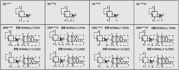
SPECIFICATION
| MODLE | MAX.PRESSURE kgf/cm 2 |
PRESSURE ADJ. RANGE kgf/cm 2 |
MAX. FLOW l/min |
MAX.BACK kgf/cm 2 |
WEIGHT(NO CONTAIN MAGNETIC VALVE) (kg) |
||
|---|---|---|---|---|---|---|---|
| DB-G03 | DBW-G03 | 320 |
1 : 7-70
2 : 7-140 3 : 7-320 |
100 | 160 | 3.5 | 3.4 |
| DB-G06 | DBW-G06 | 200 | 160 | 4.5 | 4.4 | ||
| DB-G010 | DBW-G10 | 400 | 160 | 6.0 | 5.9 | ||
FUNCTIONAL DESCRIPTION
General
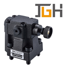
DB,DBW Pressure valves are pilot operated pressure relief valves.
They are used for the limitation (DB) or limitation and solenoid actuated unloading (DBW) of the operating pressure. The pressure elief valves (DB) consistmainly of the main valve (1) with main spool assembly (3) and pilot valve (2) with pressure adjustment element.
Pressure relief valve type DB
The pressure presentin port A acts on the main spool (3). At the same time pressure is present via the control lines(6) and (7), which are fitted with orifices (4) and (5) on the spring loaded side of the main spool (3) and at the bail (8) in the pilot valve (2). If the pressure in port A exceeds the valve set at the spring (9) the ball (8) opens against the spring(9).
The signal for this comes intemaily via the control lines(10) and (6) from port A. The pressure fluid on the spring loaded side of the main poppet(3) now flows via the control line(7), orifice bore (11)and ball (8) into the spring chamber (12). In type DB…-5X/..-.it flows intemaily via the control line (13) to tank, or , in type DB..5X/..Y..extemaily via the control line(14). Due to the orifices (4) and (5) a pressure drop occurs at the main spool(3), the connection from port A to port B is open. Now the pressure fluid flows from port A to port B whilst maintaining the set operating pressure. The pressure relief valve may be unloaded or switched over to a different pressure (second pressure stage) via port “X” (15)

